

Patch panel or direct cable in the company
How a cable run is terminated determines which component wears out during power surges, how quickly a technician can identify the run and whether an expansion starts with the documentation or with hunting for cables. We compare a cable plugged in directly, a socket without a panel and the patch panel option.
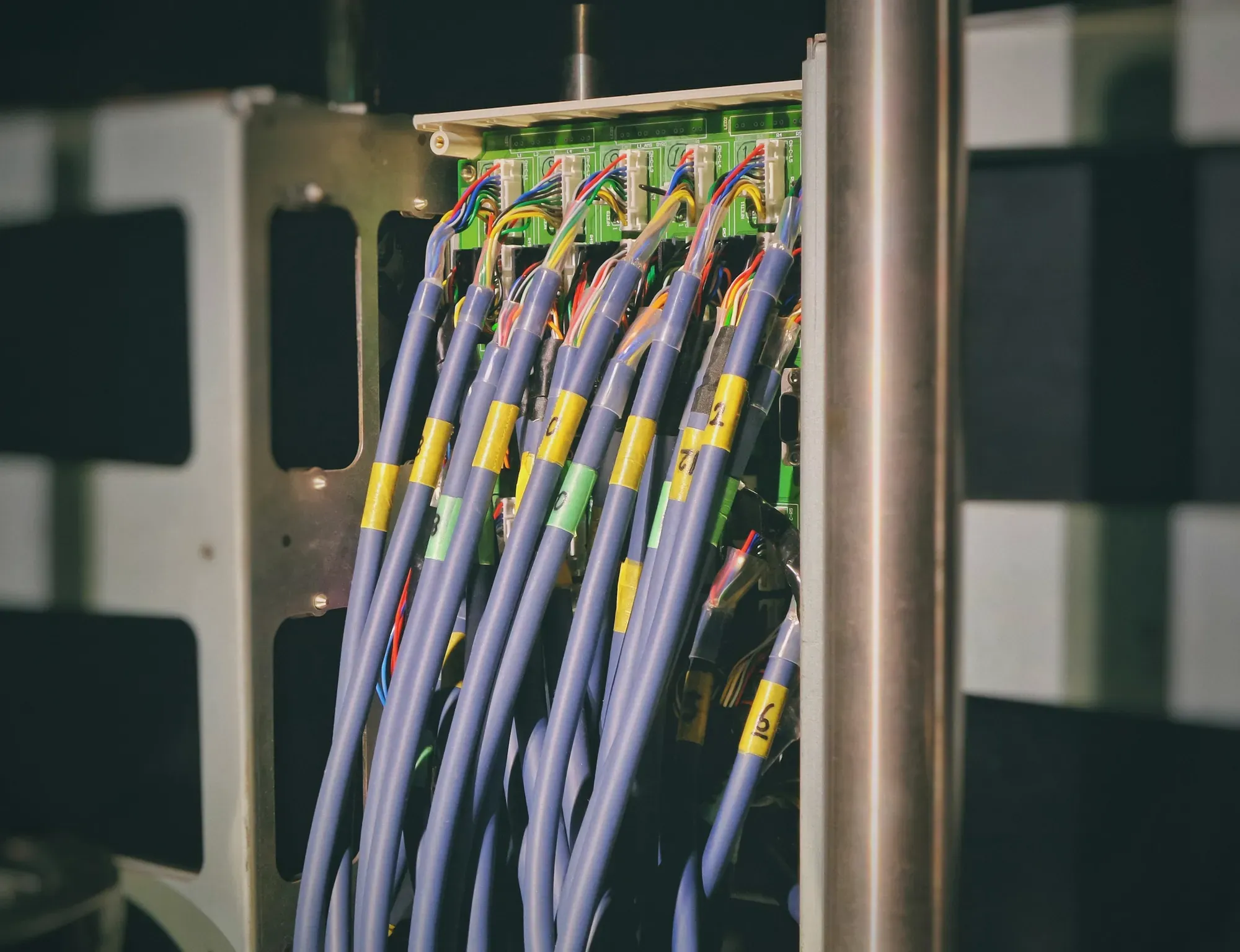
When taking over older networks, we often come across a cabinet where the cables coming out of the wall are plugged straight into the switch, with no patch panel and no labels. Every re-patch then means moving a cable hidden in the wall, and finding out which port serves which desk requires unplugging one cable after another.
How the way a link is terminated affects later changes
An installation cable routed in a wall or cable route is a permanent part, the replacement of which usually requires renewed access to partitions, ceilings or communication routes.
The patch panel and socket separate this part from the patch cords, which can be reconnected and replaced without any major interference. If the track ends with a plug plugged directly into a switch or device, any reorganization puts strain on the solid wire and its termination.
When comparing the variants at first launch, you may not notice the difference as both solutions can provide connectivity. It becomes visible later when the company changes the layout of workstations, adds access points, divides networks or looks for the cause of an unstable connection.
Three ways to terminate a link in a business
| Variant | Usable part | Technical part | Main consequence |
|---|---|---|---|
| Direct cable | the installation cable ends at the device | the cable is plugged directly into the switch | has the fewest elements, but the changes concern the fixed track |
| Socket without panel | the device is connected to the socket via a patch cable | the installation cable ends directly at the switch | only the usable side is protected |
| Socket and patch panel | there are patch cords on both sides | the permanent track ends at the panel described | easier overvoltages, diagnostics and documentation |
In a company installation that requires maintenance, the natural point of reference is the variant with a socket and a panel, because it clearly separates the building cabling from the operational layer.
A direct cable can be justified, but that choice should follow from the technical conditions and be recorded in the documentation.
What does the patch panel give you?
The patch panel creates an orderly termination point for the tracks, so the port can be marked the same as the corresponding jack in the room. The technician then sees the relationship without disconnecting subsequent wires, and the change of purpose of the point takes place on the side of the replaceable patch cable.
This is important when one socket starts serving another network segment or a PoE-powered device, because the appropriate switch port can be selected without interfering with the fixed route.
A panel also makes it easier to keep things tidy, but it does not guarantee it on its own if labels, cable management and an up-to-date port map are missing. An unlabelled panel can hide the same chaos it was supposed to remove, which is why labelling belongs in the scope of the work.
Fixed cable and replacement cable have different roles
The installation cable should remain stationary after acceptance, while the patch cable is designed for connections that change during service. Separating these roles reduces the number of manipulations with the end hidden in the partition and transfers wear to an element that is easy to replace.
When making a direct termination, you must match the connector to the wire structure and be careful because a random plug does not become correct just because the device has made a connection.
A cable left untidy can additionally burden the connector, cover ports and impede the cooling of devices, so the apparent simplicity translates into a more complex service.
When direct cable may be justified
The direct variant may be rational for a temporary track, a single device with a permanent location or a place where technical housing cannot be used. The prerequisite is an assessment of mechanical protection, serviceability and the likelihood of changes, as well as a clear description of both ends.
The decision is no longer justified when the installation covers multiple tracks, is to expand or powers devices important to the company's operations. In such an environment, saving on the passive component easily turns into additional time for each subsequent diagnosis and expansion.
It's also not a good idea to leave a provisional solution without an owner and a cleanup deadline, as temporary connections often become an invisible part of the production environment.
Diagnostics starts with track identification
When a user reports connection interruptions, the technician should quickly pinpoint the entire track, its terminations, the switch port, and the end device. Consistent labels on the socket and panel sides shorten this path because the location does not depend on the memory of the person who performed the installation.
The mere fact that the port diode is lit does not confirm the quality of the cabling, therefore acceptance should include checking the tracks appropriate to the agreed scope. If a specific class of measurement or a report from a measuring device is required, this should be recorded before the quote and then included in the report.
The scope of transferred data and responsibilities is described in more detail in the material about network acceptance protocol and as-built documentation.
PoE increases the importance of termination quality
The track can simultaneously carry data and power to the device, so the stability of the terminations affects not only communication, but also the continuity of operation of the access point, camera or other receiver.
The panel allows you to change the power port on the switch side without moving the installation cable, which facilitates load reorganization and diagnostics. However, the entire circuit, component compatibility and receiver requirements still need to be assessed, because the presence of the panel does not correct incorrect selection.
We present the method of separating the number of ports from the available power in the article about PoE power budget.
The quality is determined by the entire track
Evaluating a solution based on the number of connections alone is too simplistic because the result depends on the cable, modules, patch cords, terminations and assembly quality.
A properly made panel matched to the remaining elements is part of the planned track, while a poorly prepared plug may become its weakest point. For this reason, performance should not be promised without knowledge of the design and acceptance results.
If the business's requirements refer to a specific standard or category, the contractor should confirm the current edition of the document and the measurement procedure. The procedures for testing installed cabling and the accuracy of test instruments are described in IEC 61935-1, so it is worth stating in the contract whether acceptance includes such testing. We deliberately do not give limit values here, because they depend on the category and the edition of the standard.
Port map and connection documentation
The port map must combine the socket, panel and switch port designations with the location and purpose of the point. By also documenting tracks that are prepared but not in operation, you can prevent future expansion from having to re-check installations.
The document has to be updated after every re-patch, because its match with reality is what makes it valuable during a failure. ISO/IEC 14763-2 treats cabling documentation and administration as part of planning, installation and operation, and with ongoing support the port map is updated together with the network configuration.
What to settle before choosing a patch panel or a direct cable
- Will the track be permanent, temporary or regularly reconnected?
- Whether the environment will be expanded or divided into further segments.
- How the cable will be mechanically secured on both sides.
- Who is responsible for the labels, port map and their subsequent updating.
- Whether the track will power the device via PoE.
- What scope of inspection and documentation is to be provided after completion.
- Does the available space allow convenient servicing of the panel and switch.
The answers show whether simplification actually limits the scope or merely shifts the cost to later servicing.
How we do it
NexaIT acts as an MSP, so we evaluate the track termination method together with the architecture, maintenance and documentation responsibility. We inventory existing connections, agree on termination options, organise the markings and provide the status so that another person can check it.
We are a Zyxel Networks Partner, and we work with Ubiquiti UniFi as a technology chosen to match the project's requirements. The choice of devices is a separate decision from the quality of the passive layer, because the brand of the switch will not fix a badly terminated cable.
We tidy up link terminations as part of building and maintaining corporate networks, usually together with tidying up the rack cabinet. We carry out installation work on site in our region, including in Zielona Góra and Świebodzin.
Sources
- IEC, ISO/IEC 14763-2:2019 Information technology. Implementation and operation of customer premises cabling. Part 2: Planning and installation, https://webstore.iec.ch/en/publication/60185 (accessed 02/10/2026)
- IEC, IEC 61935-1:2019 Specification for the testing of balanced and coaxial information technology cabling. Part 1: Installed balanced cabling, https://webstore.iec.ch/en/publication/31201 (accessed 02/10/2026)
As of 2 October 2026.